
This past semester was my first semester majoring in Manufacturing Systems and I had to take an intro to C++ class. For our end of the semester project we had to use code that we learned throughout the semester to make something that’s useful and fun. My partner came up with the idea of making a bicycle tail light system that uses the accelerometer and buttons on our boards to control our system. The accelerometer controlled the blinking back light while the buttons controlled the turn signals and emergency flashers.
We also had to buy an SJSU One micro controller to run our code on so my partner and I used both of our boards to power our project. The code we created controlled the left/right turn signal, the emergency flashers (caution signal), and the automatic brake light. The caution signal flashes both turn signals to simulate emergency flashers. We programmed the tail light to blink 3 times per second when the user is accelerating and to turn solid red when the user is braking. We used GPIO (General Purpose Input and Output) pins to send these signals to our circuit. We also took advantage of the PWM (Pulse Width Modulation) pins to control the blink ability of our LEDs.
My partner had developed a basic state machine code to run through our circuit. We constructed a simple circuit using one LED on our breadboard and ran our code.
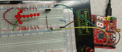
Circuit of the arrow.
After finishing the two arrows to make sure the circuit worked, we ordered mini breadboards online and a bunch of super bright LEDs. Below is a video of me testing the code before we transferred everything to our final project.
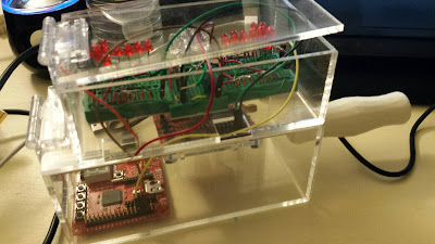
I began designing the casing that would hold our SJSU One boards and breadboards since our wires needed to be enclosed. I designed the box on Solidworks and imported the drawings into Draftsight. From there I laser cut the shapes in acrylic and glued it all together. For extra fun I 3-D printed a bike handle that is inserted onto a metal rod to simulate an actual rotating bike handle (similar to a motorcycle). One of our boards was also mounted onto this rod for the brake simulation. The rod rotates 15 degrees in either direction to support the accelerometer on our board.
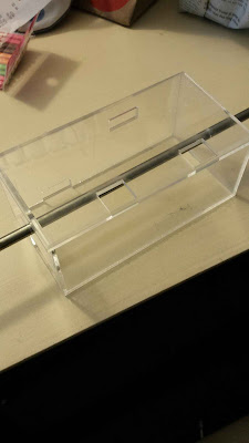
Casing for SJSU One Boards.
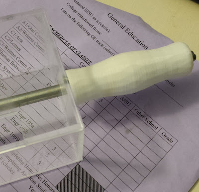
3D printed bike handle inserted onto a rod.
On either side of our brake light will be our turn signals. The breadboards sit on top of the enclosed SJSU One board box and has another box enclosing the LEDs.
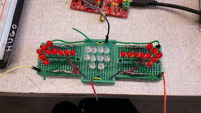
Completed circuit.
The buttons controlling the arrows will be accessible on the left side of our SJSU One board’s encasing. The final step was adding hinges to the tops of both of our boxes so we can easily move around and take out components. Since we had to write a report for this project, we created schematics for the brake light and turn signal circuit as well as a flow chart for the state machine code. While writing our code we ran into trouble combining our state machine with the basic tail light blink function so we split the code. As stated before, one board was mounted to the rod that uses the accelerometer to control the brake light and the other board uses the buttons to control the turn signals and emergency flashers.
Completed design enclosure.
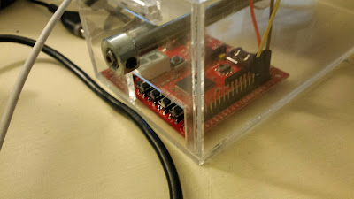
Accessible buttons for turn signals and emergency flashers.
This project was extremely fun. There was a lot of troubleshooting with our circuit and code but in the end we did awesome and got an awesome grade. I’m very excited to see what else my board can do and use it to run other projects. If you’ve never coded with C++ you should definitely try it; it’s fun and easy to pick up on. Below is a video of our working bike light system.
This took us about a week and a half to complete. Neither of us had any circuit experience either but we got it done!
If you would like to read our final report here’s the link: Bike Light System Final Report. This includes our thought process, diagrams, list of materials and the C++ code.
